
One thing about cycling about, it’s handy having a phone with apps that tell you your speed and distance, but at the cost of battery power!
And many years ago I had a bike computer that worked by GPS,, but it was hard to calibrate most of the time and as small as it was it didn’t give great information about the trip.
And I had been on the lookout for another one, but the prices seemed a bit high, ranging from the cheaper €75 end to €300 and up.
And after my last project, I wondered would it be possible to build one, I know arduino supports GPS modules so I figured that ESP32 boards would be able too, and with a quick search I found a few people used them for motorbike and car displays for accurate speed and distance. It would have been nice if someone did one for a bicycle, but I couldn’t find any.
Now me being me, not only did I want something to show me speed and distance, but temperature and air pressure would be a nice bonus.
So parts ordered and then wait a couple of weeks for it all to arrive.
And bits started being delivered it was time to start testing ideas.
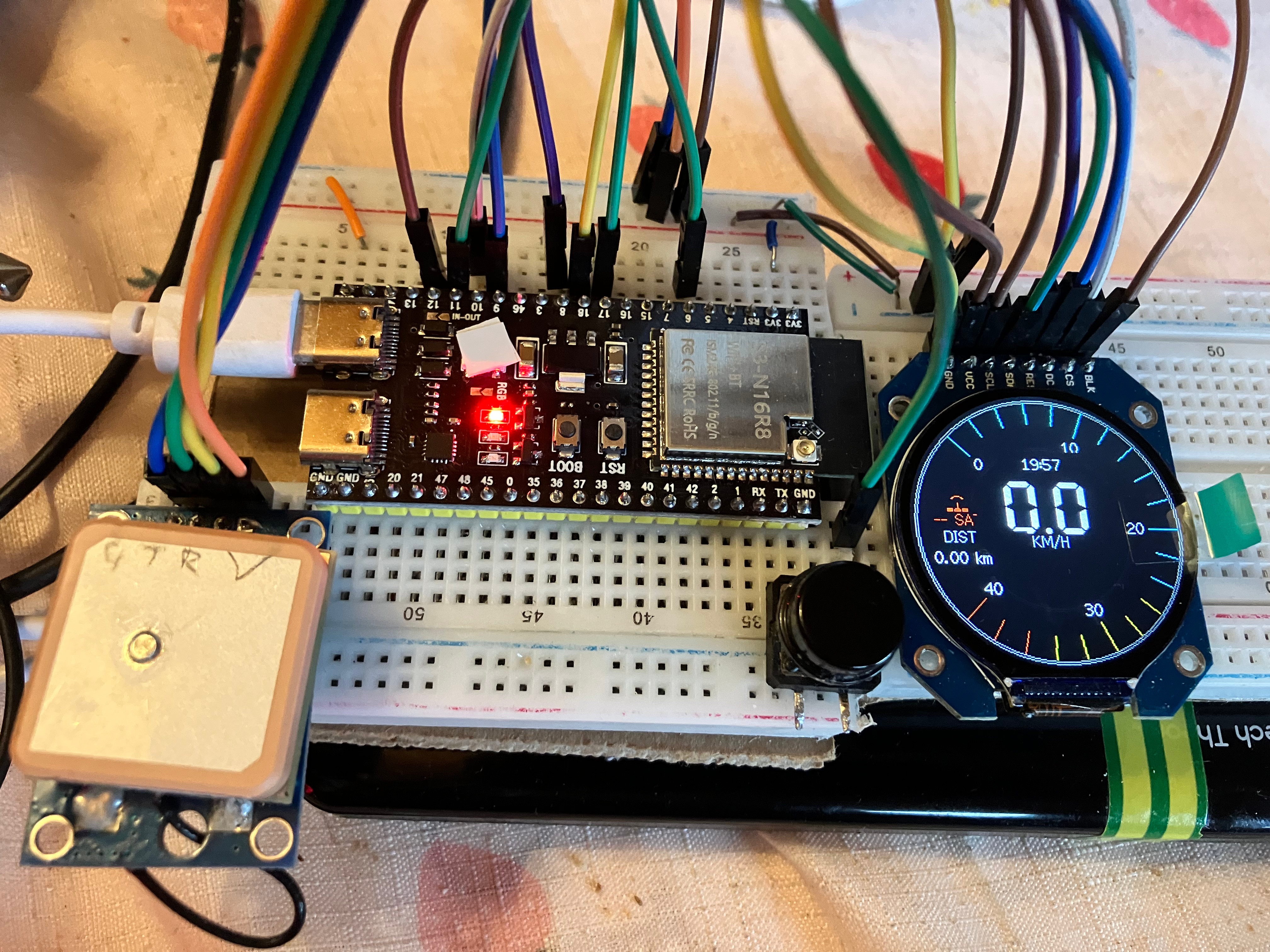
The first GPS module that arrived didn’t work, so a quick search on Amazon and I had 2 more after the weekend.
After testing them I found they worked quite well.
Then the temp/humidity/pressure sensor arrived, and again a few more tests, and that worked.
So time to test and design the code for it all, now there’s no point having all the information all on one screen, so I added “pages” that I could rotate through with a button, speed – trip – compass – clock – barometer.
But that seemed to be a bit fiddly, so added a second button, so now button 1 flicks through speed (main page) – trip -GPS info- compass- clock and back to speed, while the second button scrolls through clock – weather (showing temp/ pressure/humidity as basic text with trending data arrows to show increase or decrease in values over last few minutes) – barometer style gauge with temperature- system info.
And then added long press to the buttons, on button 1 it shuts the unit into sleep mode until pressed again, and button 2 changes theme from a dark theme to a light theme.
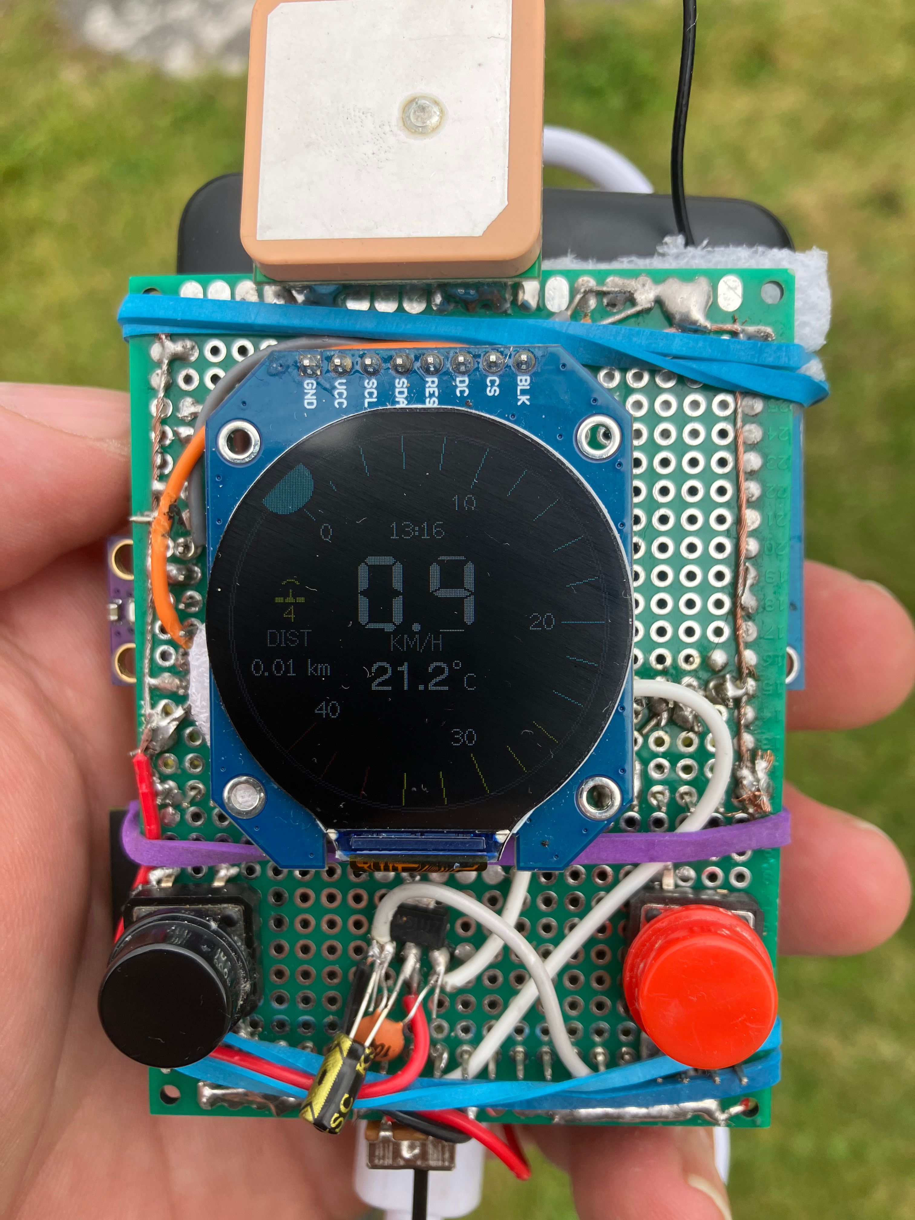
Then, there was the problem of making it mobile, so with a couple of capacitors, a voltage regulator and a LiPo battery with charging module that was taken care of, and a power switch to help save battery life when not in use.
But again, thinking pushing buttons while cycling is not ideal. I needed something like a touch sensor so I could just tap to change the pages. I knew they existed because I’ve often thought of using them for different things, but never did, so did a quick search about capacitive touch and Esp32, and it turned out they are capable of doing that without the need for sensors, just run a wire from one of the dedicated pins and it’s ready to go!! Well that was handy.
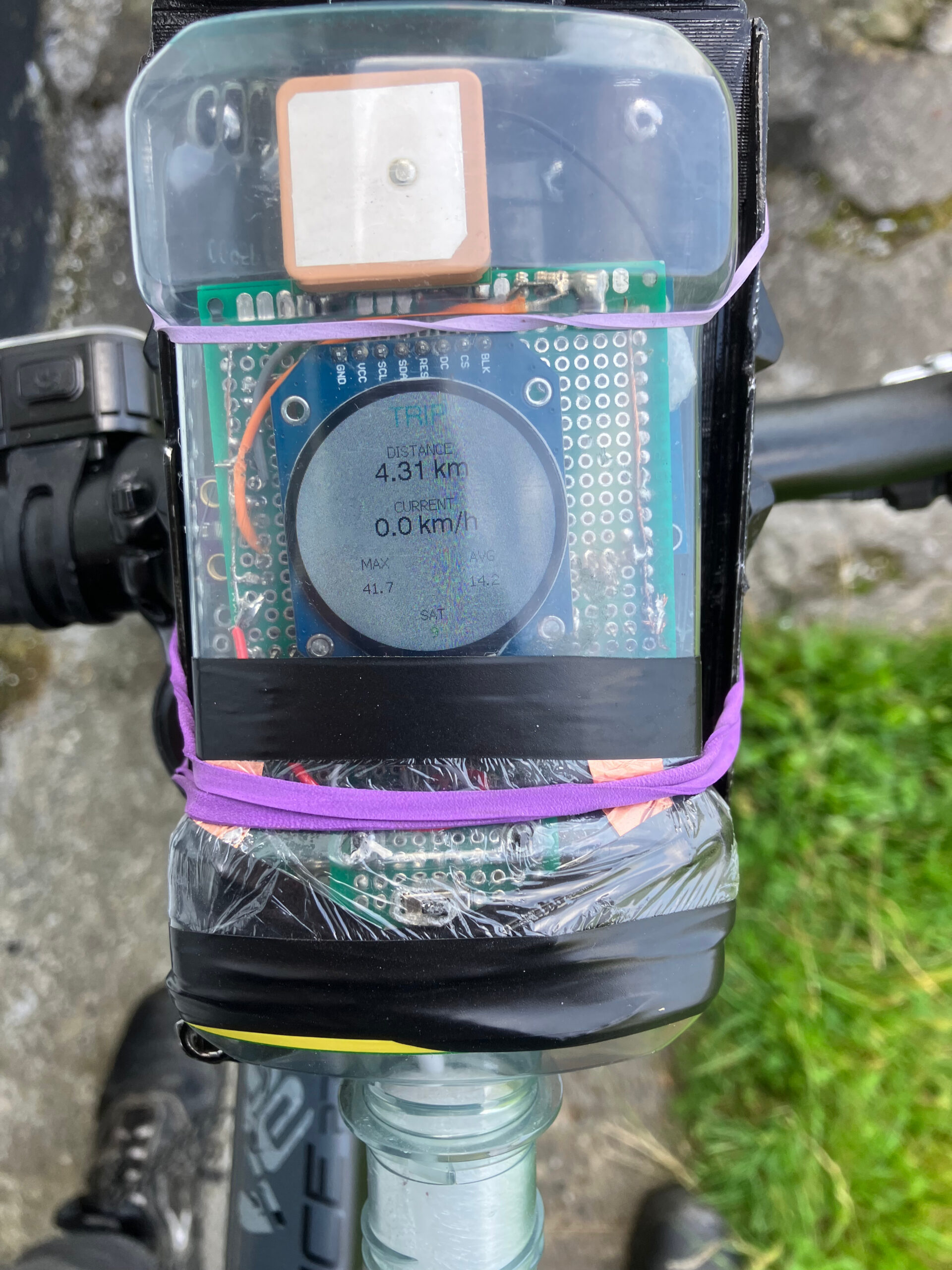
So a bit of copper tape and away it goes,, for the moment it now resides inside a Listerine bottle for a while while I do some more testing, but so far it’s going well, except for the odd short circuit happening here and there, but it seems to be going well now.
The project scripts can be got here, https://github.com/stevecrow74/BikeComputer
It’s still a work in progress so the code will change as I continue with it.
Another update: Made the whole unit more compact, and used better wiring throughout.
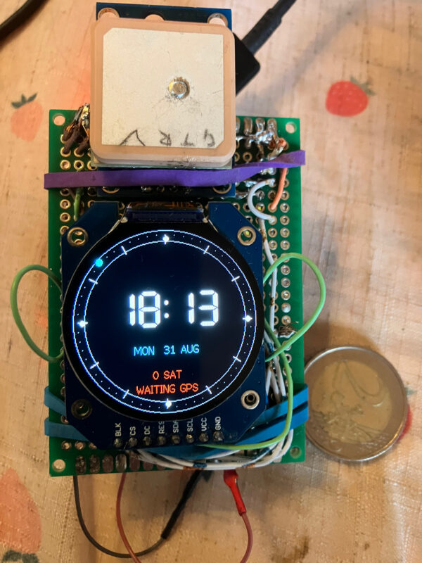
Much smaller now, and smaller buttons on the right hand side with power regulator on same board.
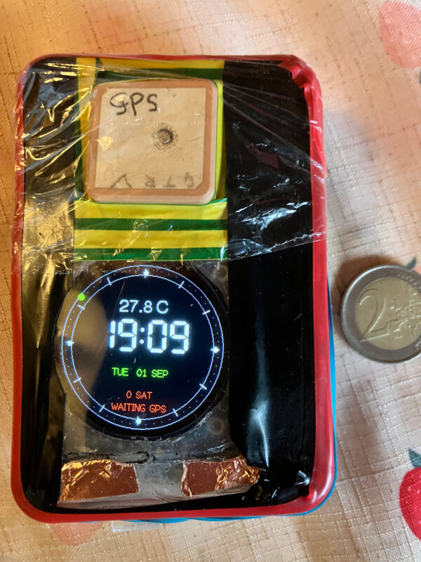
It all fits in the box the 1117 power regulators came in.
Below shows the functions of the Bike Computer taken from the GitHub README file
# ESP32-S3 Bike Computer
Firmware for a GPS bike computer based on an ESP32-S3, a 240 x 240 GC9A01 round display, a GPS receiver, and a BME280 environmental sensor. The application is built with PlatformIO and the Arduino framework.
## Features
– GPS speedometer with automatic 40 km/h and 120 km/h gauge ranges.
– GPS trip distance, maximum speed, sampled average speed, and persistent lifetime odometer.
– Detailed GPS status: fix state, satellites, HDOP, location, altitude, speed, and time.
– GPS-course compass while moving at 1 km/h or more.
– GPS-synchronised clock with Irish Summer Time adjustment and temperature readout.
– Weather display for BME280 temperature, pressure, humidity, calculated barometric altitude, and trends.
– Analog barometer from 980 to 1040 hPa.
– Speed and GPS altitude history graphs covering the latest 10 minutes.
– Dark and light display themes.
– Physical buttons and capacitive touch-pad navigation.
## Pages
### Button 1 / Touch GPIO 2
Short presses cycle through Main speedometer, Trip, GPS, Compass, Clock, and History. The next press from History returns to the main speedometer.
Hold the physical Button 1 for 3 seconds to reset the current trip. It resets trip distance, maximum speed, and average-speed totals. The lifetime odometer is not reset.
### Button 2 / Touch GPIO 3
Short presses cycle through Clock, Weather, Barometer, and System.
Hold the physical Button 2 for 3 seconds to switch between dark and light themes.
## Main Speedometer
The main page displays current GPS speed, a colour-coded gauge, GPS quality and satellite count, current trip distance, calibrated BME280 temperature, a GPS-based altitude direction arrow, and GPS-derived local time.
The altitude arrow compares valid GPS altitude samples 10 seconds apart. It indicates rising or falling only when the change exceeds 2 m; otherwise it shows level.
## Trip And Odometer
Trip distance is calculated from accepted GPS position changes between 0.5 m and 100 m. The Trip page shows distance, current speed, maximum speed, average speed, satellite count, and `ODO`.
Trip measurements and the odometer are stored in ESP32 NVS every 30 seconds and restored after reset or power cycling. The odometer increases from the same validated GPS distance segments as trip distance and survives a Button 1 trip reset. It currently displays whole kilometers.
## GPS And Compass
GPS data uses `HardwareSerial(1)` at 9600 baud. The GPS page provides fix status, satellites, latitude, longitude, altitude, HDOP, time, and speed.
The compass rotates from GPS course, so it needs a valid GPS fix and motion of at least 1 km/h. It is not a magnetic compass and cannot provide a reliable heading while stationary.
GPS time is converted to Irish local time, including daylight-saving transitions.
## Weather And Altitude
The BME280 is sampled every 10 seconds. The Weather page shows temperature, pressure, humidity, and pressure-derived altitude. Temperature is adjusted by `TEMP_CALIBRATION_OFFSET` to compensate for enclosure and display heating.
At boot, barometric altitude uses the fallback `seaLevelPressureHpa` value of 1020.0 hPa. Once a strong GPS signal is acquired, the firmware recalibrates this reference exactly once using current GPS altitude and measured BME280 pressure. Calibration requires valid GPS location and altitude, valid HDOP of 1.5 or lower, and an available BME280 pressure reading.
The calibrated reference remains fixed until the next restart. It is printed to the serial monitor as `Sea-level pressure calibrated: …`.
## History Graphs
The History page retains 60 samples in RAM, captured every 10 seconds. It shows separate graphs for speed and valid GPS altitude, covering the latest 10 minutes. The newest point is at the right of each graph.
History is not saved to flash and clears after a restart.
## Hardware And Pinout
### GC9A01 Display
| Signal | ESP32-S3 pin |
| SCLK | GPIO 12 |
| MOSI | GPIO 11 |
| DC | GPIO 9 |
| CS | GPIO 10 |
| RST | GPIO 8 |
| Backlight | GPIO 7 |
The display uses SPI2 and is configured for 240 x 240 pixels.
### GPS Receiver
| GPS signal | ESP32-S3 pin |
| GPS TX | GPIO 18 (ESP32 RX) |
| GPS RX | GPIO 17 (ESP32 TX) |
| VCC | 3.3V |
| GND | GND |
Connect TX to RX and RX to TX as shown.
### BME280
| BME280 signal | ESP32-S3 pin |
| SDA | GPIO 5 |
| SCL | GPIO 4 |
| VCC | 3.3V |
| GND | GND |
The firmware attempts BME280 I2C addresses `0x76` and `0x77`.
### Controls
| Control | ESP32-S3 pin |
| Physical Button 1 | GPIO 1 |
| Physical Button 2 | GPIO 20 |
| Touch pad 1 | GPIO 2 |
| Touch pad 2 | GPIO 3 |
The physical buttons use `INPUT_PULLUP` and should pull their GPIO low when pressed.
Touch pads are calibrated at startup. Keep both pads untouched during startup while the firmware averages 40 readings for each baseline. A deviation of 5000 counts triggers a touch.